added april 2020
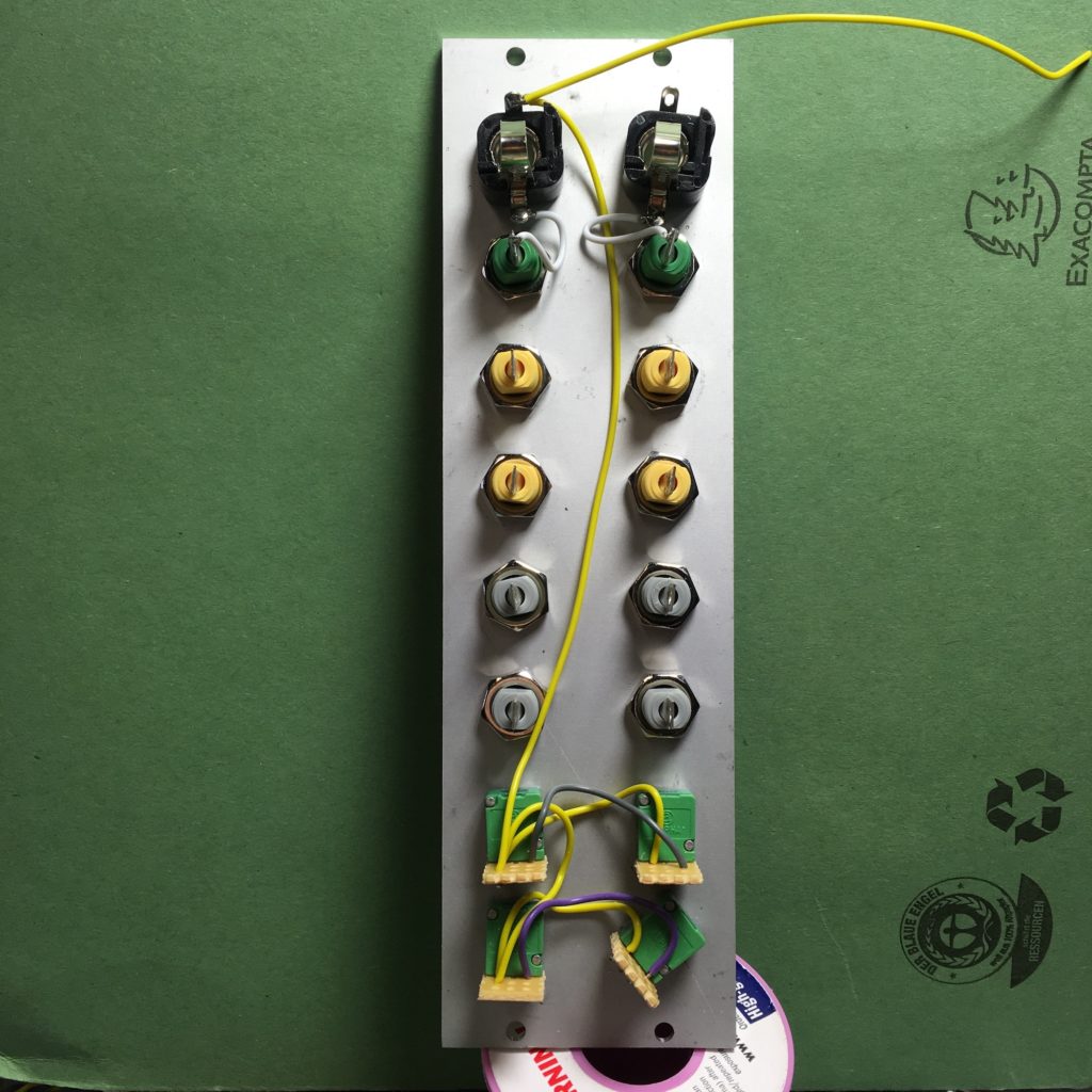
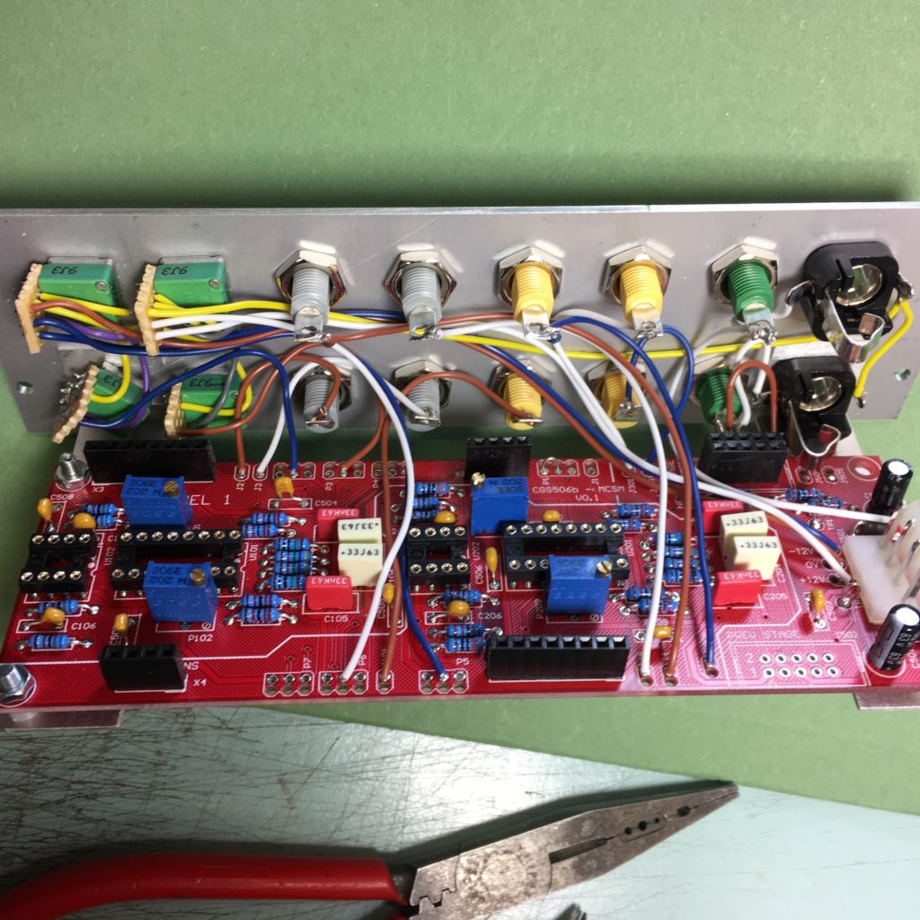
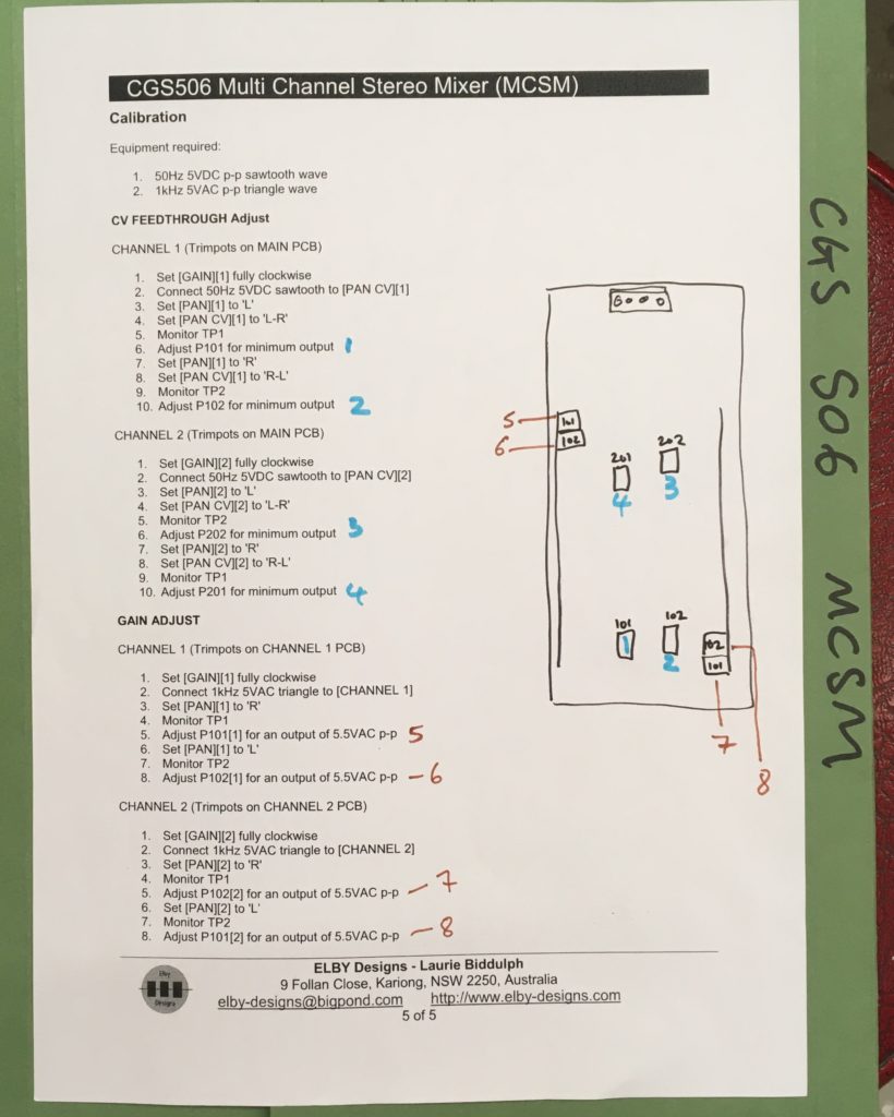
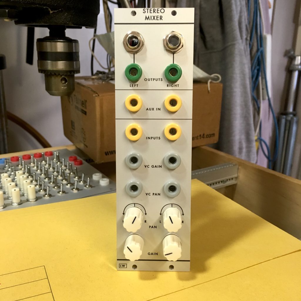 CGS 506 MCSM an be built as a replacement for the old 2″ DCSM (as on many full panels), care should be taken on build and correct selection of 1/4″ jacks is necessary (I use Lumberg KLBM3, 9mm panel hole, other may work though) – specifically the output wires should be soldered so they pass underneath the PCB (between PCB and CLee bracket) see photos below. Wiring is made easier if you put channel PCBs on headers (again see photos below)…
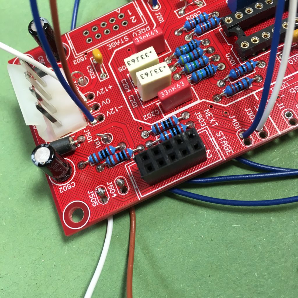 Above photo shows output wires (J504, J505) soldered so they pass under board, photo also shows resistor lead clippings for the test points TP1 and TP2 and wires for +V, -V and 0V
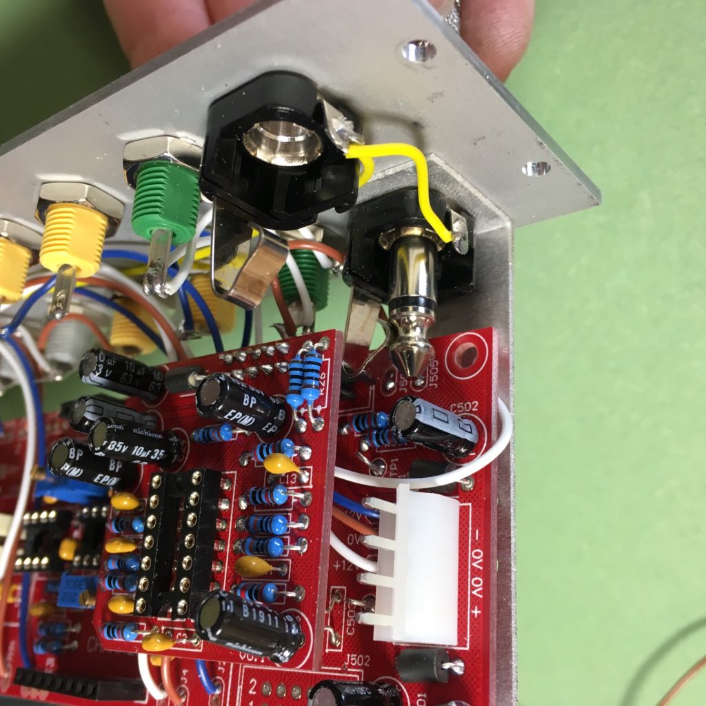 Above photo shows how tight fitment is, and how far 1/4″ jack intrudes. If care is taken no problems will occur.
Wiring diagram: Note wire link on P1
