9 Avril 2020: Add page
7th May 2020: Added advice re LM311N vs LM311P
Build an Ian Fritz Dual Teezer VCO module (either as 4″ or 5″ module):
 Parts and General Build Notes:
IMPORTANT NOTE: Use LM311N, not LM311P, the BOM previously listed LM311P, check this thread (pages 11-12) for more info:
https://www.muffwiggler.com/forum/viewtopic.php?f=17&t=112262
This build uses the new euro PCB from Synthcube, remember you need two PCB sets:
We are not going to use the panel PCB. Download BOM and build guide from above page.
Mouser BOM for two PCBs, copy and paste into Mouser BOM thing:
270-220-RC | 2
270-330-RC | 2
270-1K-RC | 6
270-1.2K-RC | 8
270-2.2K-RC | 2
270-2.7K-RC | 2
270-4.7K-RC | 12
270-6.8K-RC | 4
270-7.5K-RC | 4
270-10K-RC | 10
270-15K-RC | 4
270-18K-RC | 6
270-22K-RC | 10
270-27K-RC | 6
270-33K-RC | 2
270-47K-RC | 8
271-49.9K-RC | 2
270-56K-RC | 2
270-68K-RC | 2
270-100K-RC | 22
270-120K-RC | 4
270-180K-RC | 2
270-390K-RC | 2
270-470K-RC | 8
270-1.0M-RC | 2
270-2.2M-RC | 2
270-3.3M-RC | 2
858-67WR100LF | 2
858-67WR1KLF | 2
858-67WR5KLF | 2
858-67WR10KLF | 2
858-67WR20KLF | 2
858-67WR50KLF | 2
858-67WR100KLF | 2
810-FG28C0G1H100DNT0 | 4
810-FG28C0G1H220JNT6 | 4
810-FG28C0G1H470JNT0 | 4
810-FG28C0G1H221JNT6 | 6
810-FG28C0G1H331JNT0 | 2
810-FG28C0G1H471JNT6 | 4
810-FG28C0G1H102JNT6 | 2
80-R82DC3100AA50J | 2
594-K224K20X7RF5TH5 | 20
667-EEU-HD1H4R7 | 12
667-EEU-HD1H100 | 12
689-VN0104N3-G | 4
512-2N3904TA | 2
926-LM336Z-50/NOPB | 4
512-1N4148 | 30
78-TZX3V3C | 4
78-TZX4V3D-TAP | 4
78-TZX5V1D | 4
623-2743001112LF | 12
595-TL071CP | 4
595-TL072IP | 2
595-OPA134PA | 4
926-LM311N/NOPB | 4
926-LM741CN/NOPB | 4
595-OPA2134PA | 4
595-OPA2227PA | 2
575-144308 | 24
575-199316 | 2
594-222236521104 | 2
BOM notes:
Sometimes it is cheaper to order 10 of something than 1. The Teezer uses 1/8″W resistors. BOM does not include CA3280’s, 2K Tempco, Dual Transistor (Q1, Q2), any banana sockets, any pots, knobs, standoffs, connectors, switches. Nor does it allow for matching ie you may want to buy more of those components that need matching. It does include all other IC’s, all R’s, all C’s, all diodes etc.
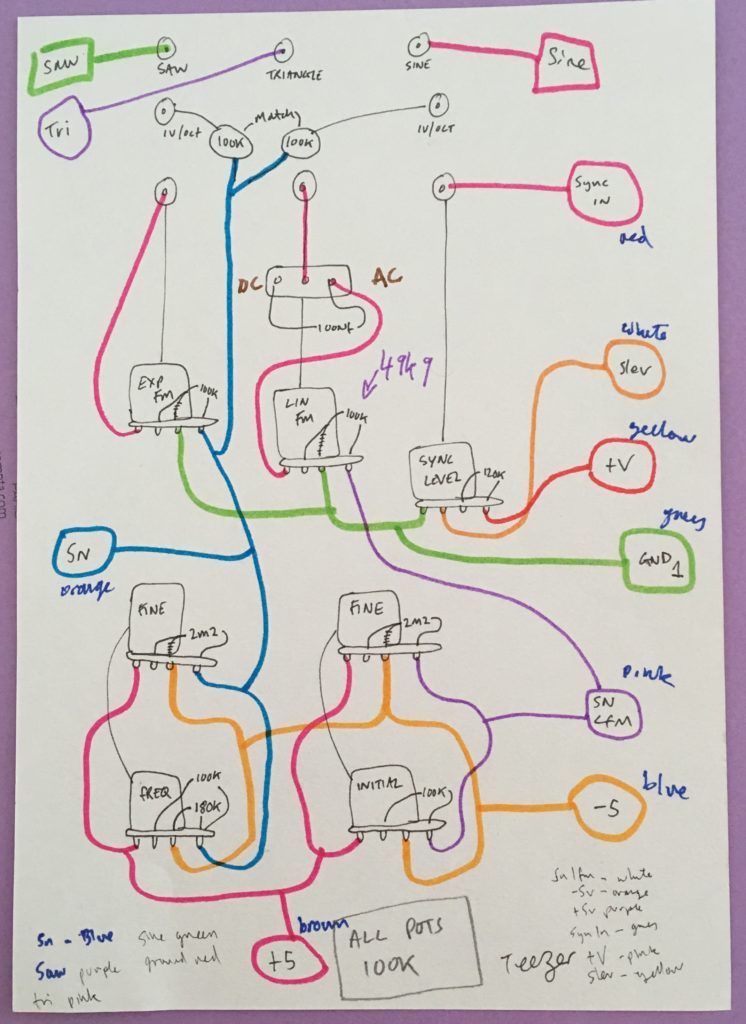
Wiring Diagram:
Build two PCBs:
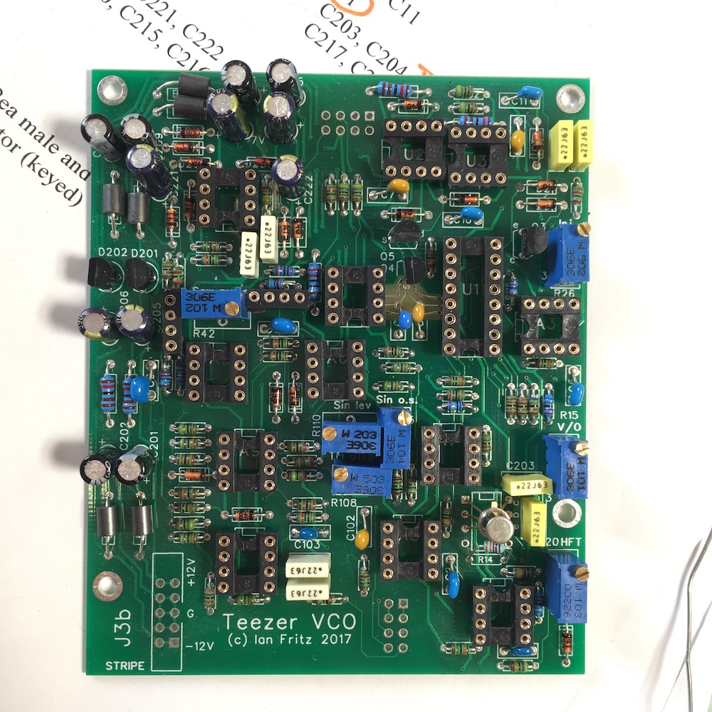 Prepare pots with stripboard (cut with scalpel both sides, snap with pliers, sand with fine emery paper, clean with IPA, solder, check for bridges)
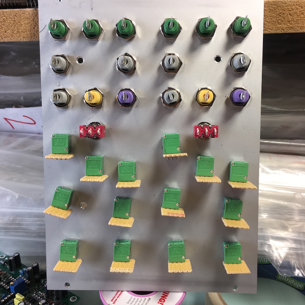 Solder panel components (resistors, capacitors, see wiring diagram – remember to match the pairs of 1V/Octave 100K resistors for each VCO)
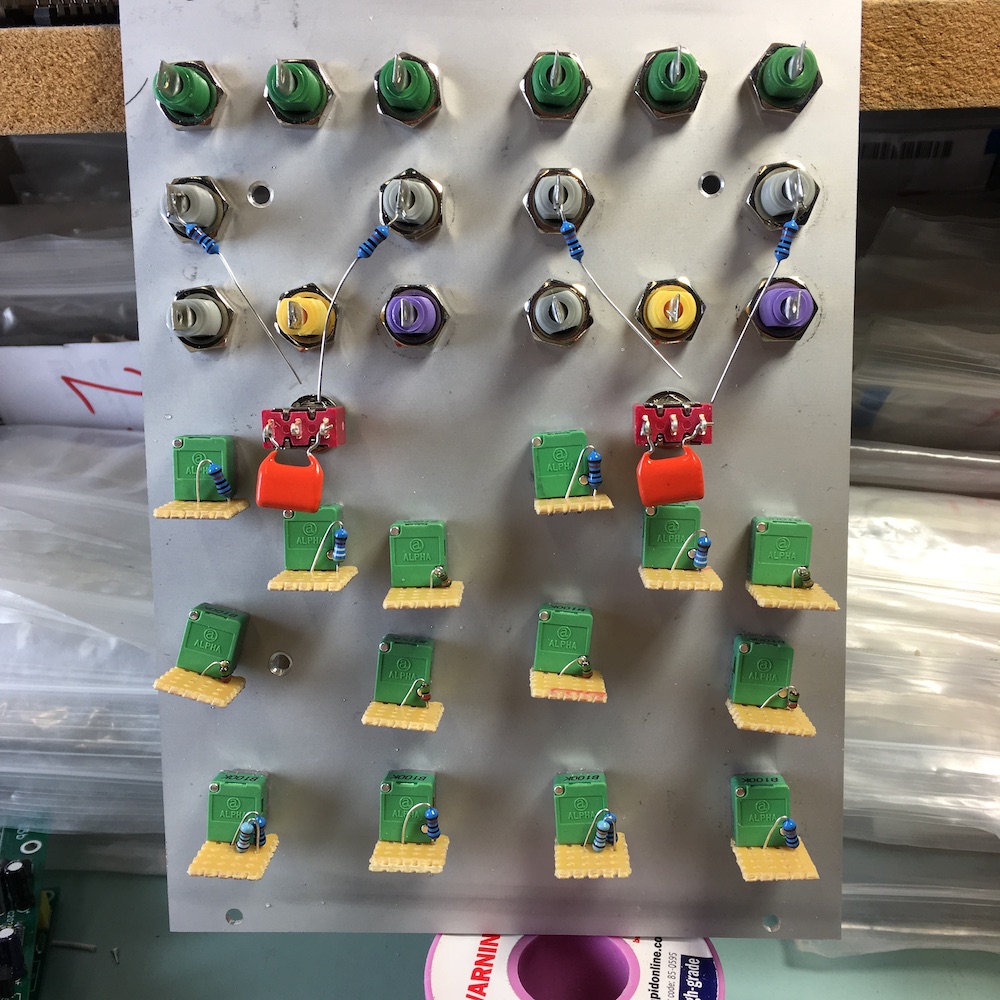 Lay in panel wiring (see diagram)
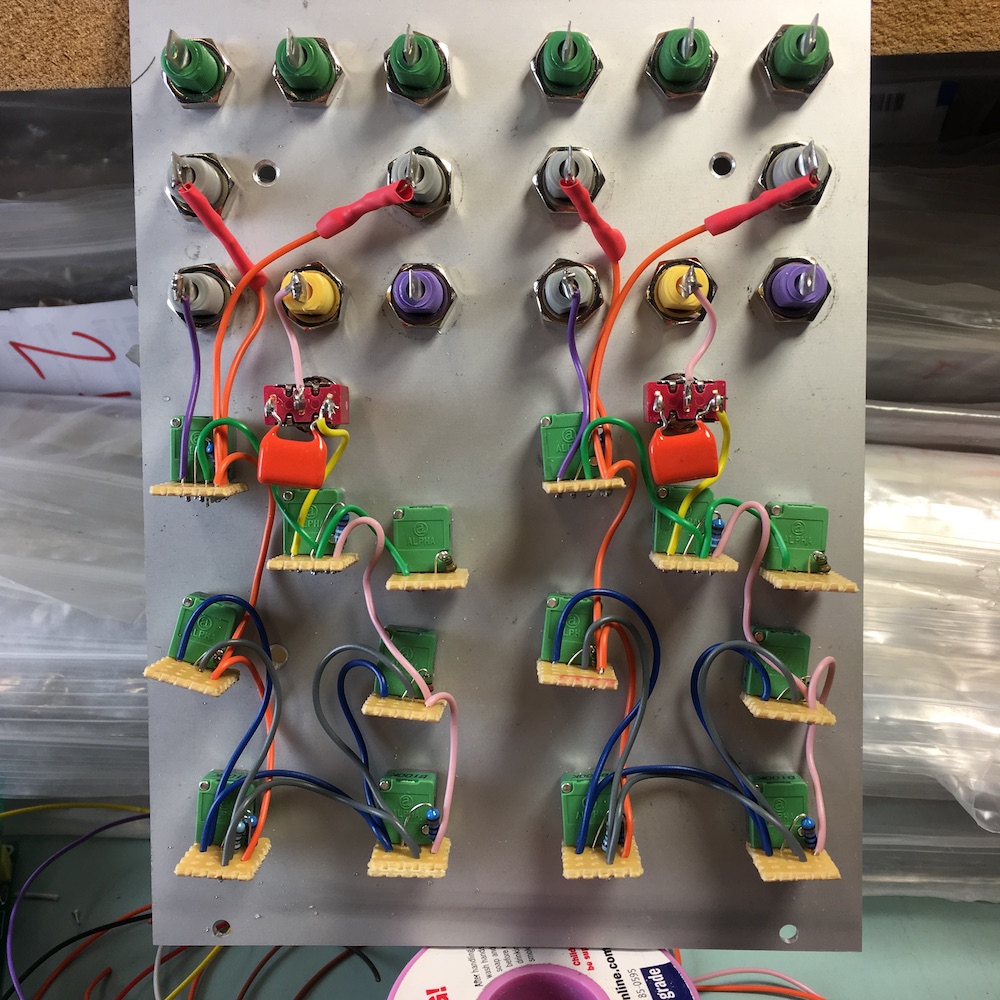 Solder 11 long wires to each PCB:
Saw, Sine, Tri, SynIn, Slev, Snlfm, Sn, +5V, -5V, +V, GND1
Attach PCB at right angles and solder first PCB to panel, ensure cables go direct to panel and then to component (right-angles) – ie NEVER cut too short!
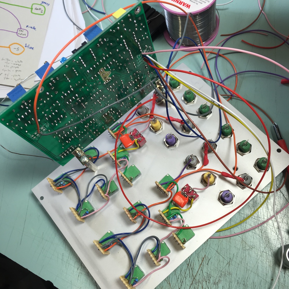
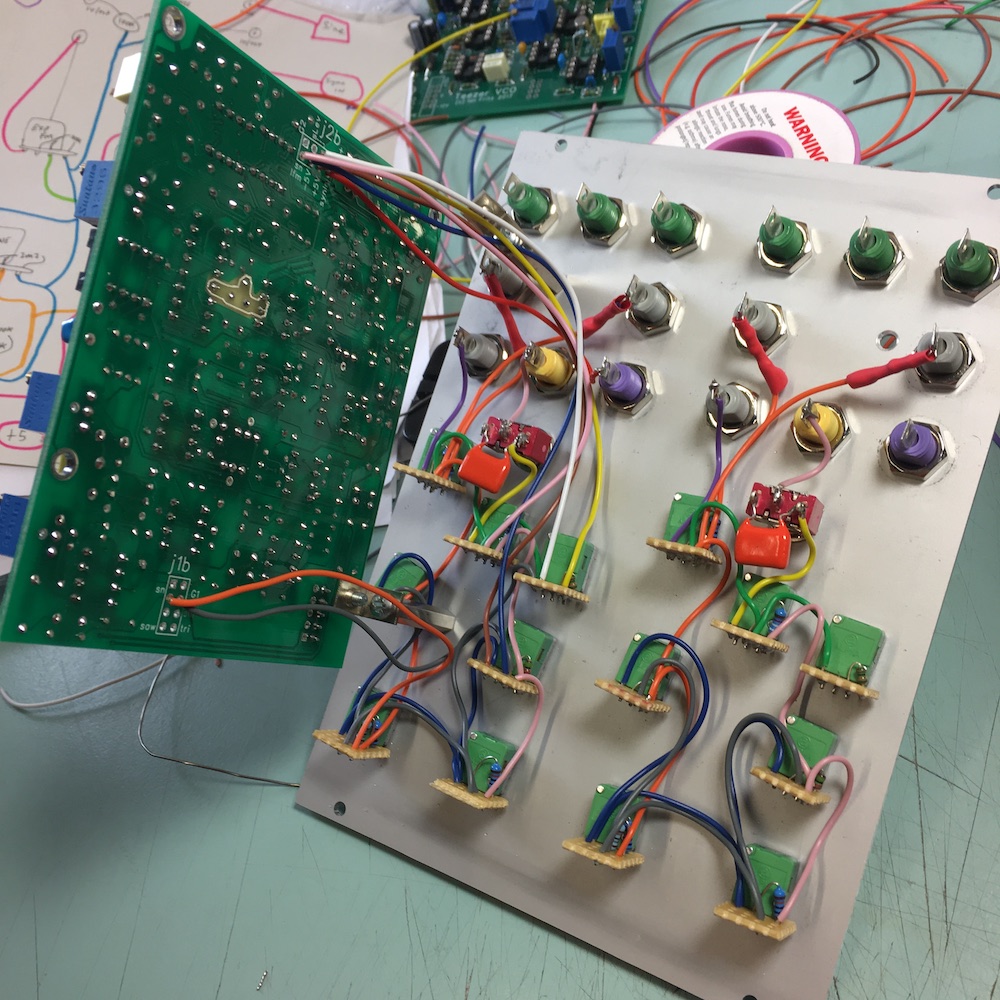 You could power up and test module now – ensure that whatever you use to hold PCB is not shorting any points on PCB. I would suggest powering up without chips and checking voltages first.
You could entirely finish and calibrate this VCO before continuing if you like.
TBC
